Cross Coupling Cable Protectors
CCCP - Cross Coupling Cable Protectors
Customized Protection
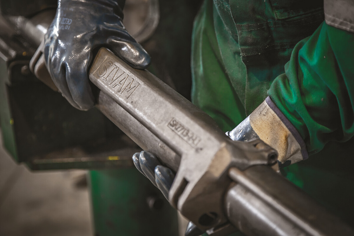
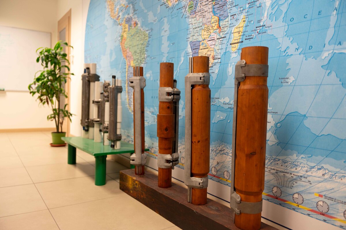
For over 30 years, Sivam has been manufacturing clamps for every possible combination of cables and geometries. Thanks to its extensive experience, each clamp is fully customized to meet the specific needs of clients and meticulously designed at the headquarters in Italy, ensuring exceptional protection for control lines and cables during running-in-hole operations.
- Custom solutions: Compatible with every possible size of tubing, casing drift, and cable/line combination.
- Limitless range of cable clamps: Designed to ensure and protect ESP cables and multiple Control Lines/Injection Lines in well completion.
- Specialized clamps: Includes MLE clamps for ESP pumps and a variety of metallurgies tailored to specific needs.
- Project and quotation in a few hours
Maximum quality and efficiency
Our manufacturing process adheres to the highest standards of quality and precision. Utilizing advanced techniques and premium materials, we guarantee that each clamp meets the rigorous NACE MR-01-75 standards, ensuring resistance to harsh environments and corrosion.
Whether it’s a standard or specialized clamp, our products exemplify Italian engineering excellence, tailored to exceed industry expectations and the demands of our clients.
Project and quotation in a few hours

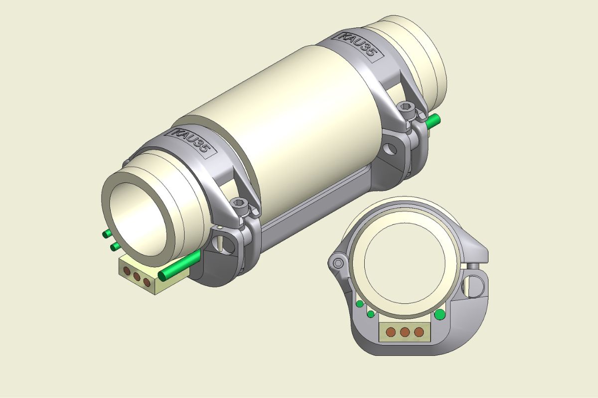

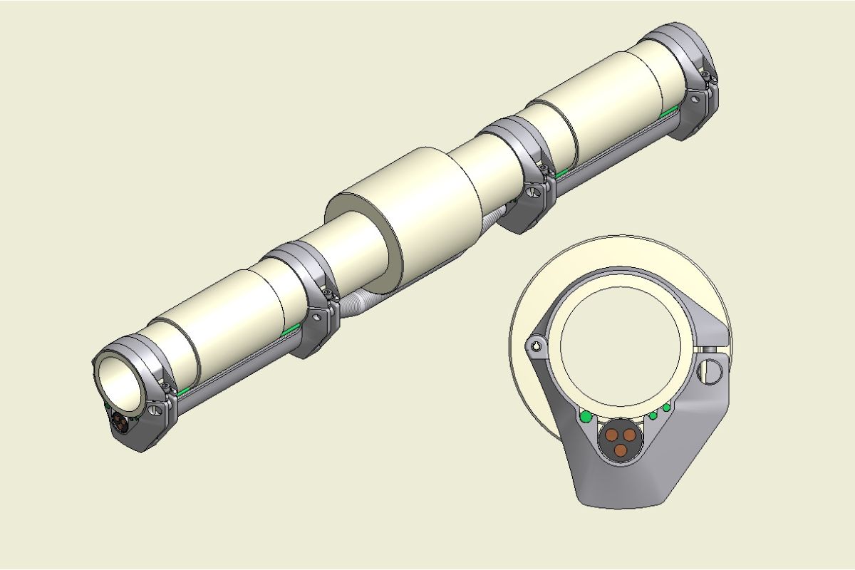
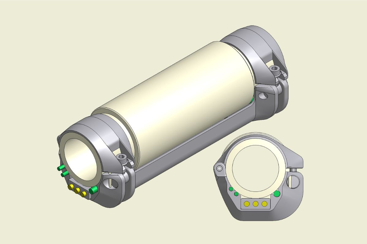

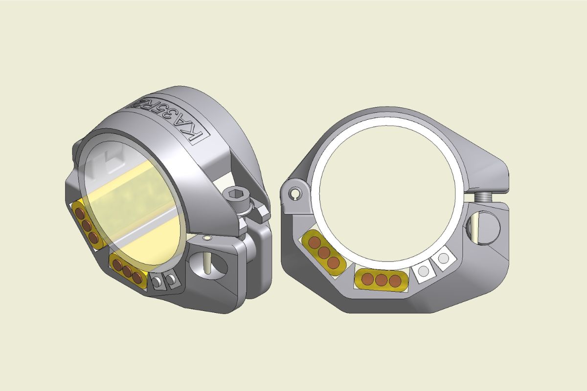

Cross Coupling Cable Protectors
Technical characteristics
Studied to have minimum overall dimensions, we design the strap type protector which can satisfy even the smallest drift size;
The ends of the protectors, are linked using a WIDE RANGE CURVATURE and SMOOTH ANGLE to allow for an easier running in the well;
Built in SOFTER METAL than the casing, in order to avoid damage to the casing while running in hole. They can also be made in a range of other materials including stainless steel, and plastic. They can also be teflon coated. Designed to AVOID the control line and cable from twisting, crushing and also from erosion against the tubing coupling and the casing
Installation of the CONTROL LINE AND CABLE PROTECTORS is made SAFE AND EASY thanks to the hookup of the clamp-protector; Equipped with a "CIRCLIP" to avoid that the locking screws unscrew and fall into the well; Every component can be SUBSTITUTED or REPAIRED if necessary.
How we design our cccp
Sivam designs Control Line Protectors following specific guidelines to meet customer requirements.
The size and shape of the protectors are tailored based on tubing dimensions, the number and type of control lines or cables, and casing drift.
-
Streamlined and
efficient design -
Fast and
easy installation -
Strong grip
on tubing -
Prevents twisting
and erosion
-
Minimixes sticking
during deployment -
Based on
tubing dimensions -
Customized for cables
and lines -
Designed for
casing drift
Why choose cccp Sivam spa
Sivam designs Control Line Protectors following specific guidelines to meet customer requirements.
The size and shape of the protectors are tailored based on tubing dimensions, the number and type of control lines or cables, and casing drift.
Design
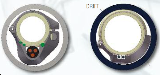
If the client’s “drift needs” are not limited than SIVAM can offer ALL CAST CONTROL LINE AND CABLE PROTECTORS, with protector body and clamps, both manufactured using “LOST WAX” or “SAND” casting:
If the diameter of the drift is limited than a strap type solution can be used, this type of CONTROL LINE AND CABLE PROTECTOR is made from a casted body and plate clamps which thickness ranges from 2-2.5mm
Protection
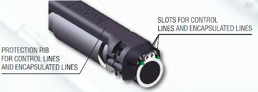
To protect the control line and cables while running in, they are locked in the slots, as can be seen in the figure below, between the body of the protector and the tubing.
Installation
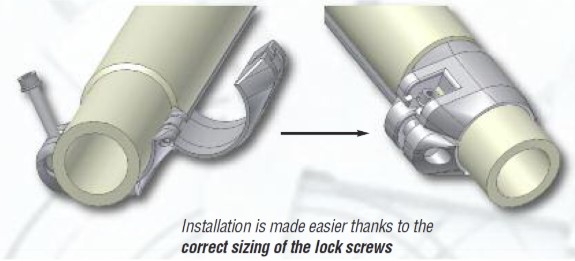
Installation of the CONTROL LINE AND CABLE PROTECTORS is made easy thanks to the connection of the clamp on the protector as can be seen below:
Test
Visual and functional inspections are carried out on the entire production.
Load tests are performed upon request.
The dimensional test is an overall check that all components conform to the design of the protector.
The correct assembly and the overall dimensions (which must be less than the drift) are checked.
The functional and load tests verify that the protector assembly – control line – tubing can support the stress of the running in the well.
Sivam carries out sliding tests on the protectors mounted on the tubing and slippage tests on the control line and the tubing.
Sliding test
After having assembled the protector onto the tubing, using a hydraulic press, an axial load is applied allowing the protector to slide on the tubing. This load is incremented until the protector slides.
Slippage test
After having assembled the protector onto the control line and tubing, each control line is pulled and the slippage value or strength needed in order for the control line to slide against the rest of the system is measured.